Method for detecting abnormal conductivity of the Dolphin XP005 probe and milling cutter
This post will help you judge if the conductivity of the Dolphin XP005 probe and milling cutter is abnormal.
Here are the steps:
Step 1.
Disassemble the back cover and pay attention to the cover wiring when disassembling.
Step 2.
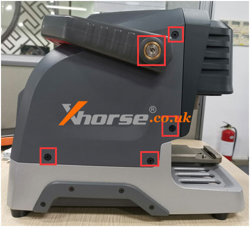
Remove the back cover, you can see these things, take off the wire harness, and remove the Phillips screws (see Figure 1).
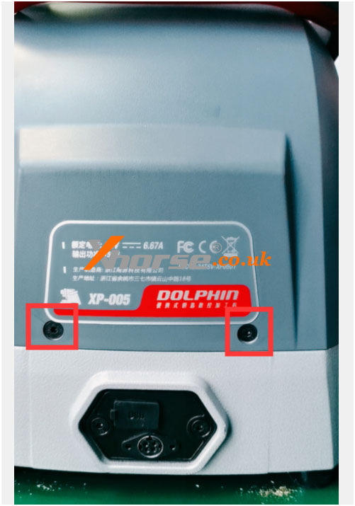
Take out the rubber pellets from the front of the device.
There are screws inside.
This strip needs to be removed (Figure 2)
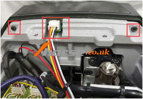
Figure 1
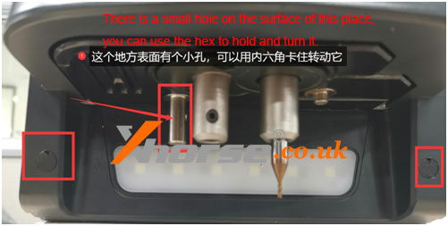
Figure 2
Step 3.
Use a flat-blade screwdriver to turn the lead screw, align the Z-axis and the outer cover on a horizontal surface (as shown in Figure 3 and Figure 4), remove the Z-axis housing after alignment (as shown in Figure 5), and place the probe next to it.
Remove the screws (as shown in Figure 6).
Remember to be careful when removing it.
There is a conductive wire inside (as shown in Figure 7).
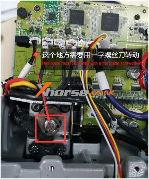
Figure 3
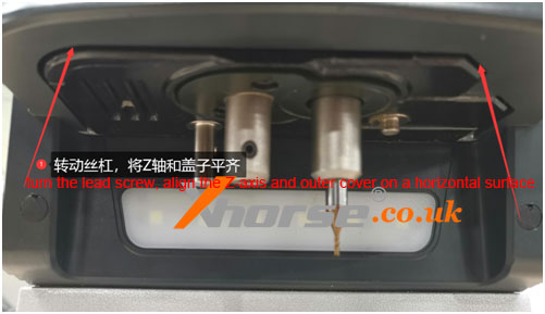
Figure 4
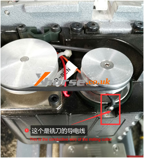
Figure 5
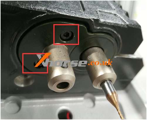
Figure 6
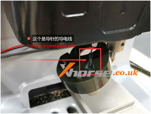
Figure 7
Step 4.
If the above steps are all done, the next step is to check whether the conductive wires of the milling cutter and the probe are conductive or short (as shown in Figure 5 and Figure 7), which needs to be combined with the mainboard to detect. (Figure 8) (or plug in the cable on the mainboard, and then check whether the conductivity is normal)
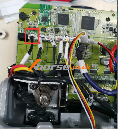
Figure 8
Step 5 (conductivity of cutter).
Loosen the 3 screws of the Z-axis (as shown in Figure 9), and then tighten the two screws (as shown in Figure 10).
Push these two screws to the inside until there is a gap.
This is to take out the shaft (as shown in Figure 11), press your finger on the position of the milling cutter hole, and push it up with a little force and then observe whether the white paper inside is broken (as shown in Figure 12) if it is broken, it needs to be replaced.
If it is not broken, observe whether there are iron filings in the bearing hole.
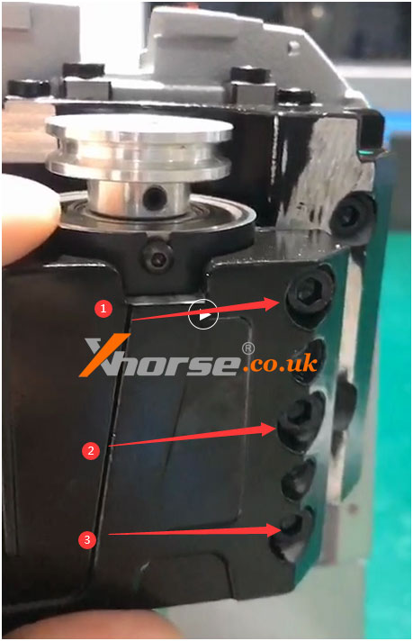
Figure 9
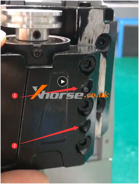
Figure 10
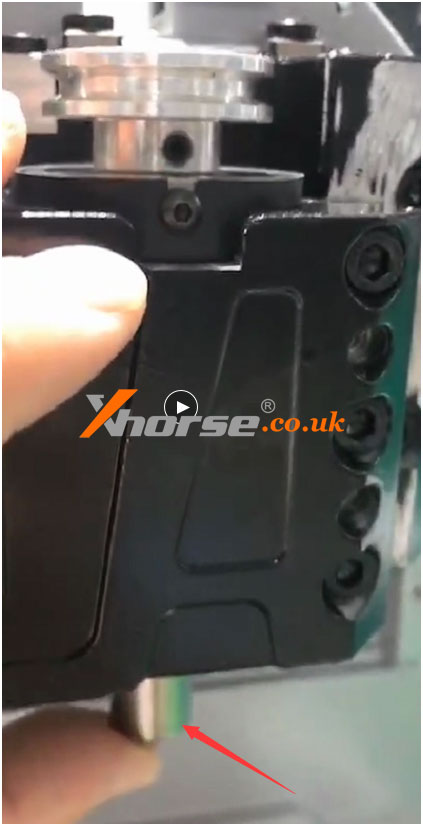
Figure 11
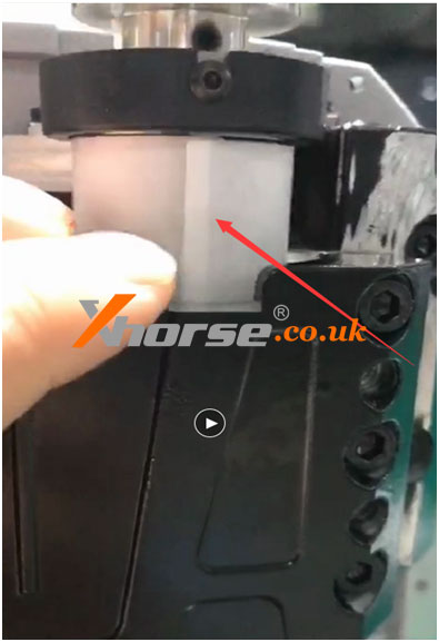
Figure 12
For more technical services, please contact
https://www.xhorse.co.uk/